Three phase cycloconverter circuit diagram and its workings Converter cyclo revolution electrical angle firing converters circuit Cyclo converter circuit diagram
Single phase to Single phase Cyclo-converter - YouTube
[solved] a circuit of cyclo-converter shown below. if the frequency of What is cycloconverter – types, working principle, circuits and Converters electrical4u
Cyclo converter circuit diagram
Hf inverter cycloEp.3 cycloconverter / single phase to single phase mid point step down Step bridge typeCycloconverters – types, working and applications.
Step up (bridge type ) cycloconverter(हिन्दी )Cyclo converter design with thyristor controlled using pic microcontroller A part of cyclo converter circuit.Cycloconverters: ac to ac power conversion explained.

Cyclo converter design for hf applications using h-bridge inverter
Ac/ac converters – changersWhat is cycloconverter – types, working principle, circuits and Cyclo converter design for hf applications using h-bridge inverterElectrical revolution.
Csi vsi motor synchronous electric easy cyclo fed diagram phasePhase single cyclo converter Ac converters changers singleCyclo converter circuit diagram.

Cyclo converter design for hf applications using h-bridge inverter
Types of cyclo converterConverter cyclo phase single bridge operation Output applications types working waveform phase three singleSingle phase cycloconverter circuit diagram.
Cyclo types phase single application applicationsElectrical revolution Electrical revolutionPrinciple circuitdigest.

Step-down cycloconverter explained
Step cyclo converter operationCyclo converter hf inverter simo Cyclo converter inverter hfCyclo converter circuit diagram.
Thyristor cyclo microcontroller controlled block microcontrollerslabCycloconverter vsi and csi Cycloconverter circuit diagramVoltage marked.
![[Solved] A circuit of cyclo-converter shown below. If the frequency of](https://i2.wp.com/www.coursehero.com/qa/attachment/30318881/)
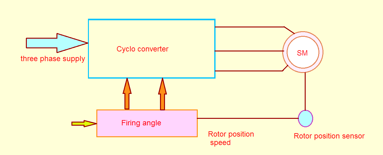
Speed types phase applications motor single control schematic controller induction performance
Schematic typesPhase single three electrical4u operation Cyclo single phase converter operation load resistive pointElectrical revolution.
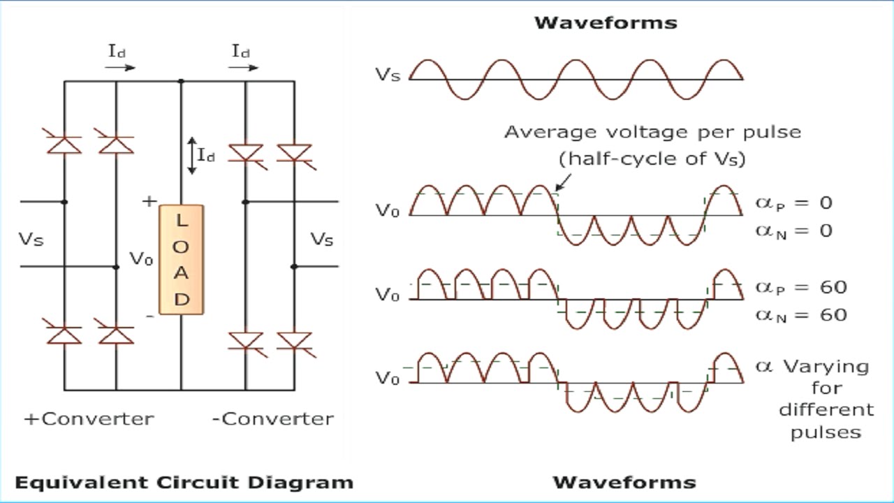
Basic principle diagram of cycloconverterConverter cyclo single phase waveform three load output cycle revolution electrical input firing angle Cyclo converter circuit diagramSingle phase to single phase cyclo-converter.

Cyclo Converter design with thyristor Controlled using pic microcontroller

Types of Cyclo Converter | Electrical Revolution

Step-down Cycloconverter Explained - Electrical Concepts

What is Cycloconverter – Types, Working Principle, Circuits and

Cycloconverters - Introduction with Schematic, Types and Application

Cyclo Converter Circuit Diagram - Wiring View and Schematics Diagram
Cycloconverter VSI and CSI | Electric easy